For Home
Take control of your home's energy. Store solar power, reduce costs, and enjoy greater independence.
All Products
Helpful Tools
Channels
Stories


Take control of your home's energy. Store solar power, reduce costs, and enjoy greater independence.
All Products
Helpful Tools
Channels
Stories
Smart energy solutions that put cost control and energy security back in your hands.
All Products
Helpful Tools
Channels
Stories
We offer a fully integrated system for installers, streamlining from design to post-installation services.
Start Here
SolisStorage service keeps you on the sunny side - expert support for all our systems.
Self-Service
Technical Support
Community & Insights
With the continuous growth of installed PV capacity, there is a clear mismatch between PV generation periods and load peak-demand periods, causing grid absorption capacity for feed-in power from existing PV plants to approach saturation in many countries. In response, multiple countries have introduced policies that restrict PV projects from feeding power into the grid-measures include sharply reducing feed-in tariffs to very low levels or even to zero/negative prices, while also capping the feed-in power at the grid-connection point, in some cases limiting it directly to zero. These policies have significantly reduced the returns of PV projects that cannot achieve local consumption.
Against this backdrop, a growing number of existing grid-tied PV projects are retrofitted with energy storage systems (ESS). By storing the energy that cannot be locally consumed during PV surplus periods and releasing it when PV output is insufficient, the storage system not only helps improve the overall utilization of PV generation but also effectively enhances project returns.
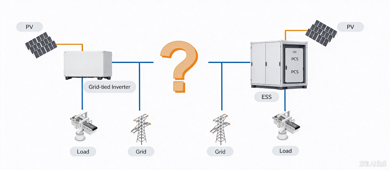
2.1 Original PV Grid-Tied System and Storage System Cannot Operate Cooperatively
The original PV grid-tied system and the storage system to be added lack a complete PV-storage coordinated solution. This results in the inability to perform coordinated monitoring and control and incomplete display of system energy information. Conventional solutions require installing a data collector and an EMS, leading to a long communication chain, slow control response, and substantial commissioning work during installation, including EMS and data-collector configuration.
2.2 Multiple Roof-Mounted Grid-Connection Points Prevent System-Level Generation/Consumption Monitoring
This concerns projects with multiple PV grid-connection points—for example, within the same factory or farm, PV systems are installed on different buildings, connected to the grid locally, and then aggregated at a main grid-connection point before feeding into the grid.
2.3 Typical Application Scenarios
One or more PV grid-tied systems are installed on site—for instance, different livestock units in a farm, or the roofs of different buildings in an industrial park or plant—each with its own PV grid-tied system; the systems are separately bused and then aggregated into the main grid-connection distribution box.
As in the case study below, Building 1 and Building 2 are different factory buildings at some distance from each other, with PV installed on their roofs and a grid-tied inverter installed near each building. The inverters' AC outputs are aggregated at the main grid-connection point.

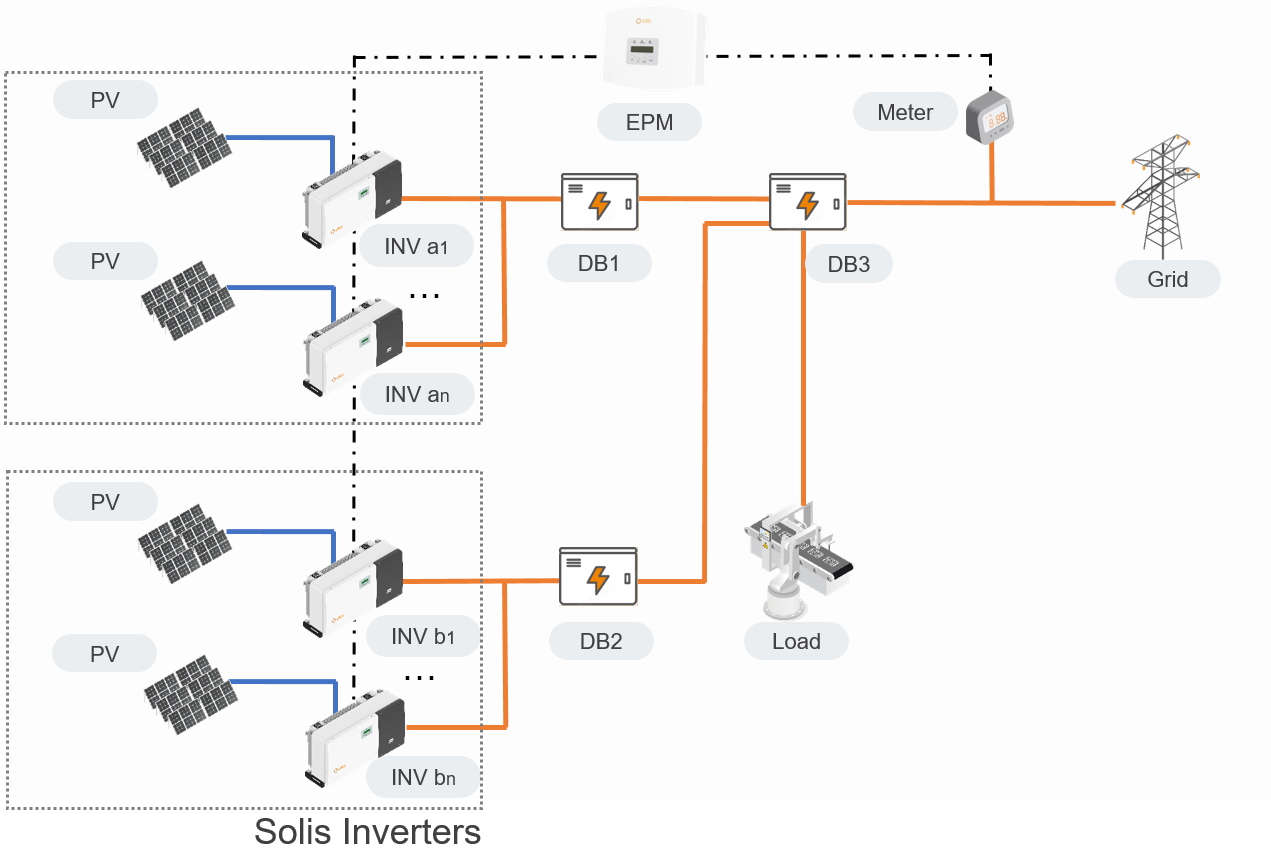
Figure1: Original System Diagram
At this point the system contains multiple generation sources—including multiple PV grid-tied generation sources, storage system generation or storage, load, and grid consumption—yet system-level monitoring cannot be achieved across the whole system. End customers cannot obtain accurate generation and consumption information, nor accurately understand how much benefit the added storage system delivers.
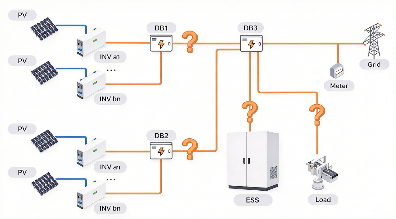
Figure2: System Diagram after Adding Storage
The above typical applications correspond to four scenarios respectively:
1)Single/multiple PV inverters connected, Solis PV inverters, without zero-export/power-limiting control;
2)Single/multiple PV inverters connected, Solis PV inverters, with zero-export/power-limiting control;
3)Single/multiple PV inverters connected, third-party PV inverters, without zero-export/power-limiting control;
4) Single/multiple PV inverters connected, third-party PV inverters, with zero-export/power-limiting control.
We adopt an innovative control architecture: the hybrid inverters in the SolisStorage EverCore integrate a powerful EMS control function, adaptable to various complex application scenarios. Deployment is fast, requiring no modification of the original wiring and no installation of additional controllers.
Scenario 1: Single/multiple PV inverters connected, Solis PV inverters, without zero-export/power-limiting control
The SolisStorage EverCore C&I ESS uses RS485 to perform data acquisition on the Solis grid-tied inverters and to exercise overall system integration control over PV capability and storage energy.
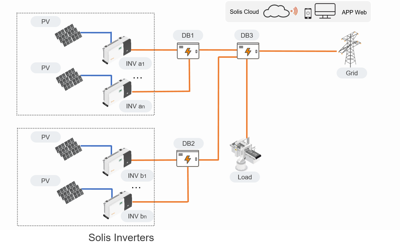
Figure3: Original System Diagram
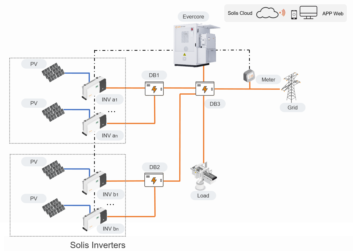
Figure4: System Diagram after Adding Storage
Scenario 2: Single/multiple PV inverters connected, Solis PV inverters, with zero-export/power-limiting control
The SolisStorage EverCore C&I ESS uses RS485 to perform data acquisition on the Solis grid-tied inverters and to exercise overall system integration control and monitoring over PV capability and storage energy; it replaces the original EPM with the storage inverter to achieve system zero-export control.
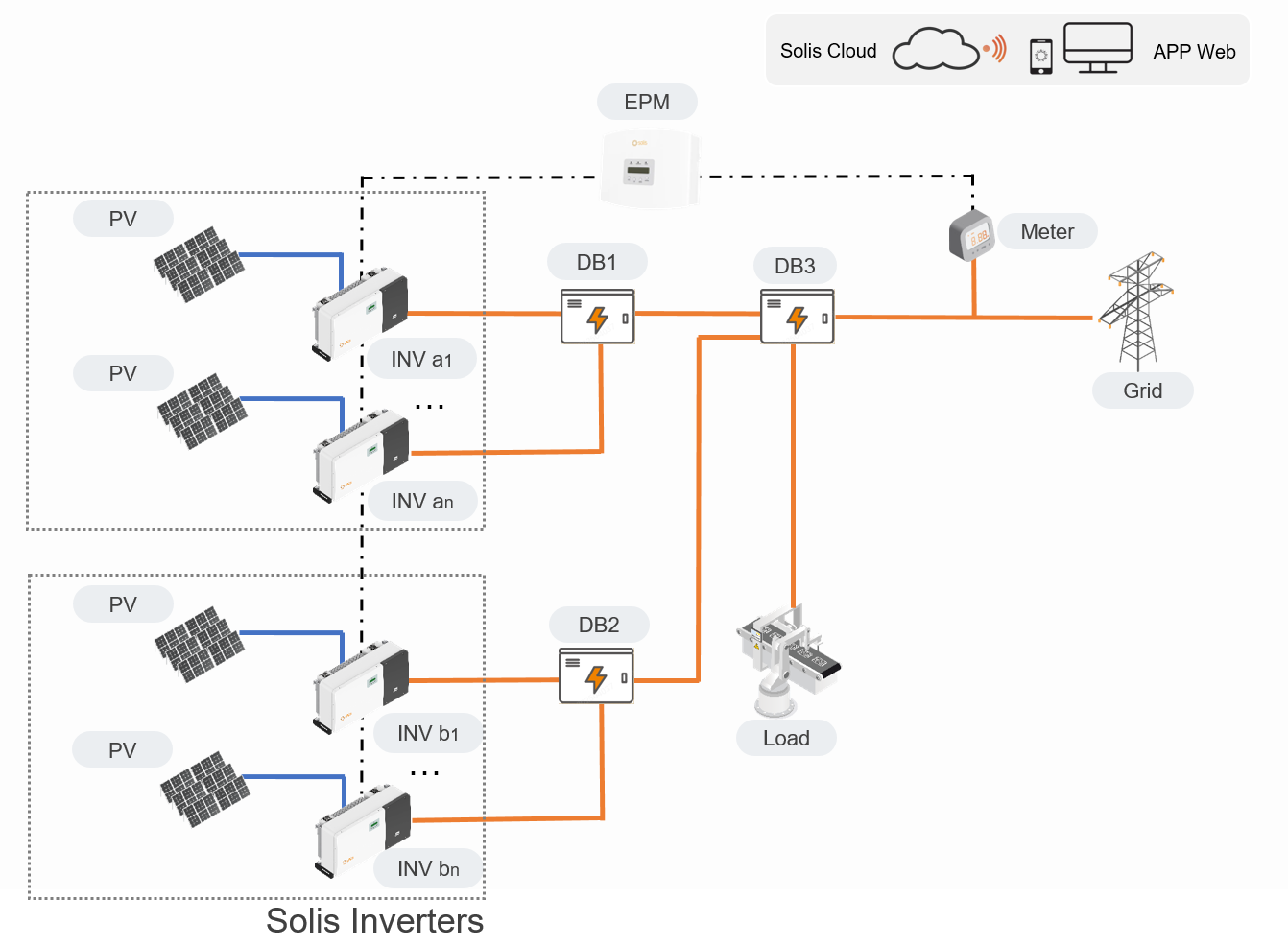
Figure5: Original System Diagram
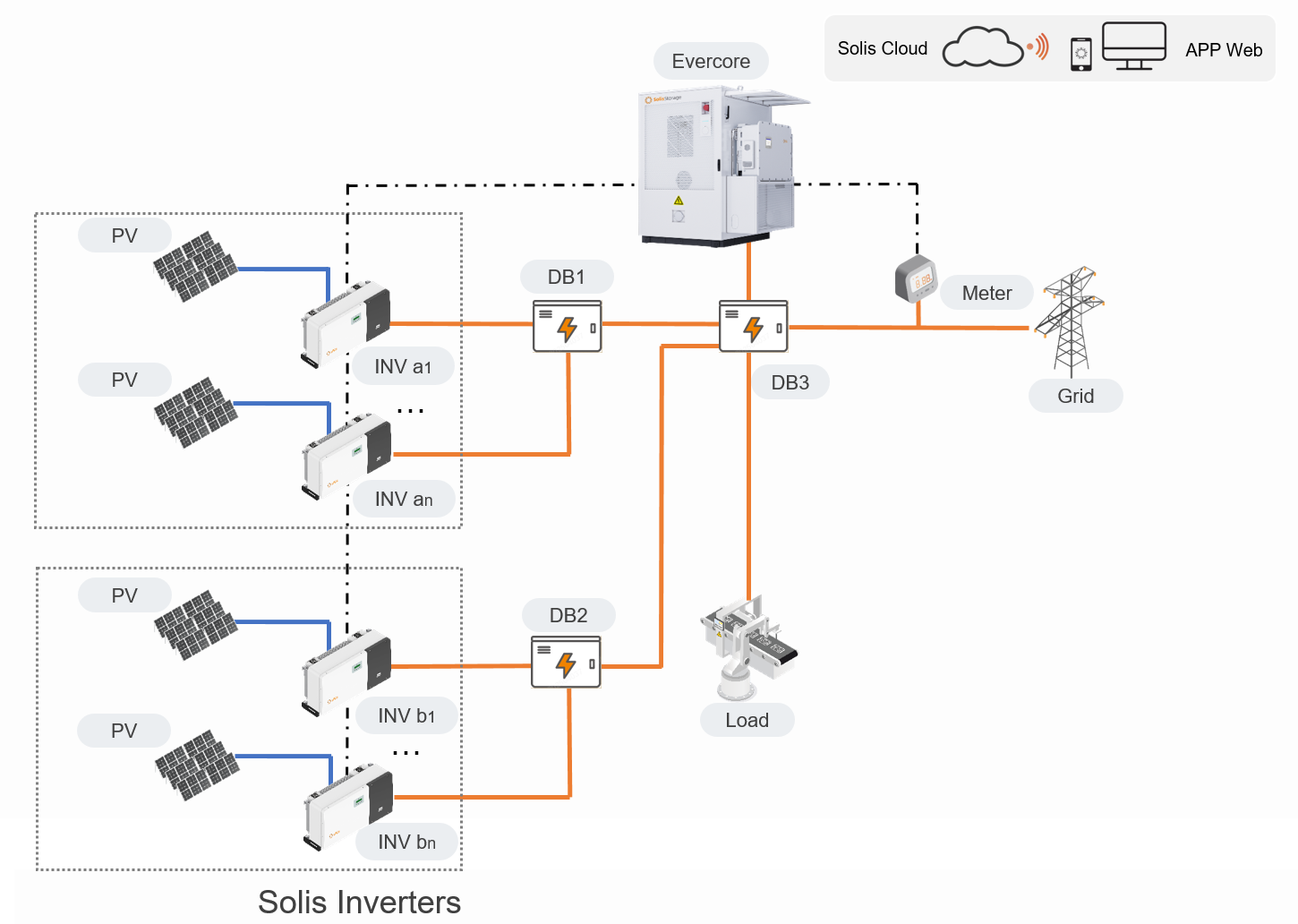
Figure6: System Diagram after Adding Storage
Scenario 3: Single/multiple PV inverters connected, third-party PV inverters, without zero-export/power-limiting control
The existing PV grid-tied project uses non-Solis inverters with no zero-export restriction, so the SolisStorage EverCore C&I ESS can be added directly and system monitoring performed via meters. It supports acquiring data from up to 6 meters; the energy interface displays total PV generation power, and the device interface can show each meter's power and energy separately.
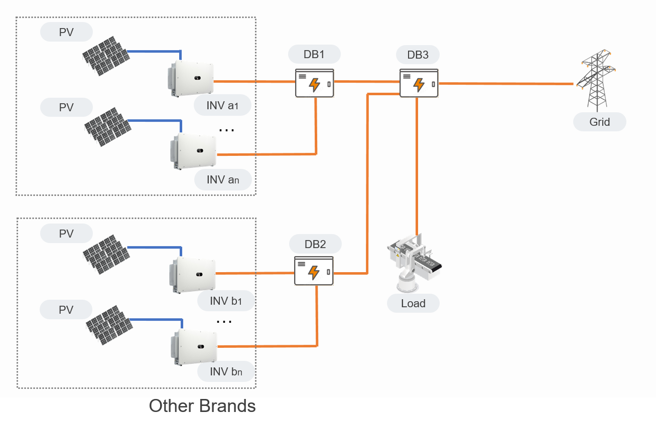
Figure7: Original System Diagram
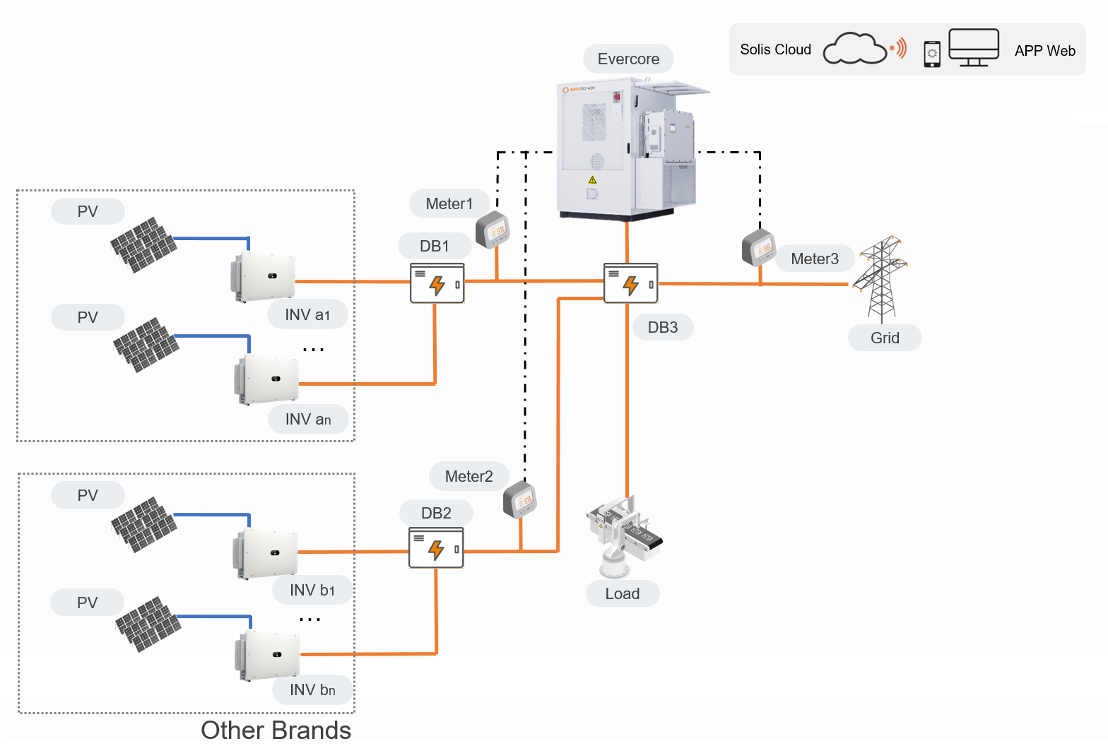
Figure8: System Diagram after Adding Storage
When PV power exceeds load power, the storage inverter automatically detects the feed-in power. Surplus PV power is prioritized to charge the battery, making full use of the PV energy.
Inquire here: www.solisstorage.com/en/intouch
I have read and agree to the Privacy Policy.
Newsletter
Join the SolisStorage newsletter for product news and updates.
I have read and agree to the Privacy Policy.
Online ChatOffice Hours:24/7
Start ChatSales Support
sales@solisstorage.comTechnical Support
service@solisstorage.com